
Chapter 12
The sensor, and closing up
The sensor arch goes on last. Its pad reaches over the centre of the wheel, a hair above the face of the filter disc, with the magnet looking up at it through a hole; that is why it could not go on before the wheel. Once its cable is plugged into the board, the panel goes up under the box and the machine is closed.
What you need
Parts
- 2×M3 screw · collar clampM3 × 14, hex socket head (12.4 mm needed under the head)
- 2×M2 screw · AS5600 moduleM2 × 4, countersunk head (4.0 mm needed under the head)
- 1×sensor coverprinted, ASA
- 2×M2.5 screw · sensor coverM2.5 × 8, hex socket head (7.0 mm needed under the head)
- 1×CAT5 cablesolid, Ø5.6 - sensor to board
- 3×M3 screw · panelM3 × 8, countersunk head (8.0 mm needed under the head)
- 1×U3 AS5600 magnetic encoder moduleround Ø16.85 flattened to 15, a row of 8 pads; needs the VDD5V-VDD3V3 bridge, after which it no longer takes 5 V
- 1×C3 ceramic capacitor100 nF (104), 16 V or more - on the module's pads, not on the board
Tools
- 2.5 mm hex key
- 2 mm hex key for the cover screws
- a PH0 screwdriver for the countersunk module and panel screws
- one 2.5 mm cable tie
Step 1 The bracket, over the wheel and onto the collar
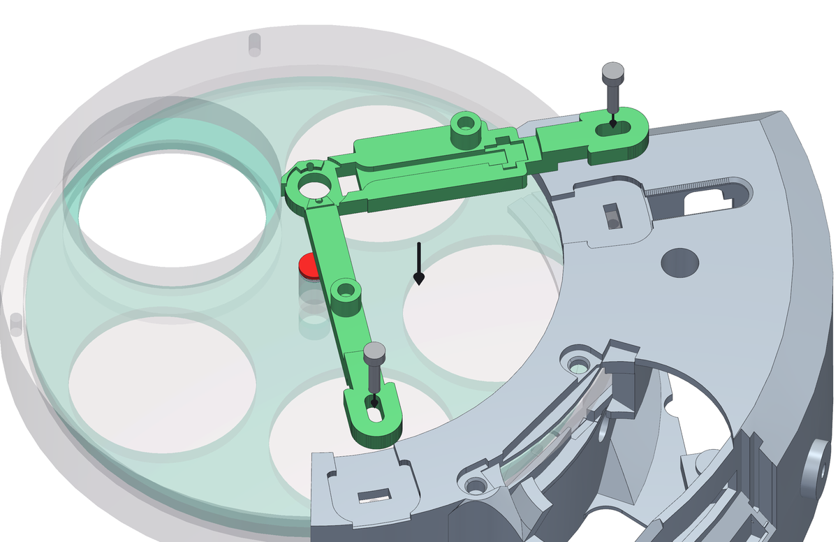
- Before it goes on, thread a 2.5 mm cable tie through the pad on the arm that faces the box: down one of the two slots, along the groove underneath, up the other one. Leave it open. Once the bracket sits on the wheel there is no way under the arm - the groove is what lets the tie pass there without lifting the bracket off the wheel.
- Lower the bracket so that its pad comes down over the magnet and its two feet land on the collar flange.
- M3 × 14 screws, one through each foot and the collar flange under it, into the threaded M3 holes already in the rear plate of the wheel body, on the telescope side.
- Do not force it down. The pad rides just above the face of the disc: if it touches, something underneath is not home - most likely the wheel is not all the way into the collar.
Step 2 The AS5600 module, on its two screws
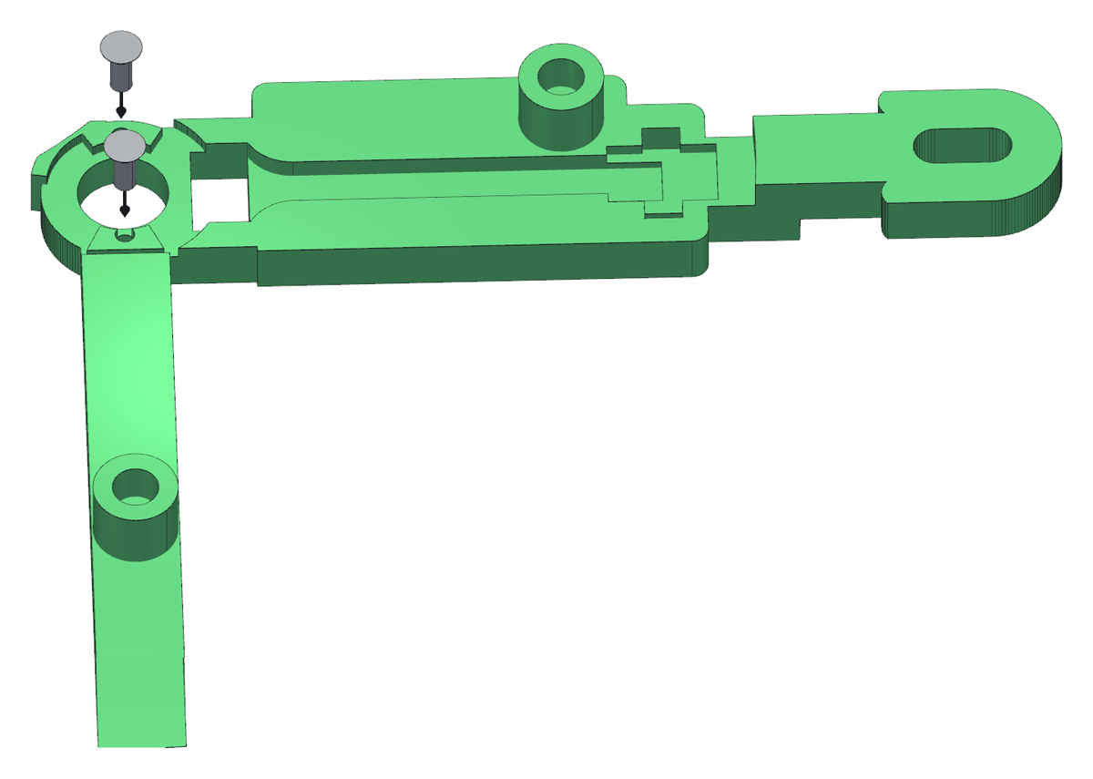
- The AS5600 module drops into the seat in the top of the bracket, chip side down, over the hole that looks at the magnet. It leaves about 1.2 mm of air between the chip and the magnet.
- Fix it with two M2 × 4 countersunk screws, through its two holes into the pilot holes of the bracket, with a PH0 screwdriver. They form their own thread in the plastic: tighten them snug, no more.
Step 3 The cable, then the cover over the module
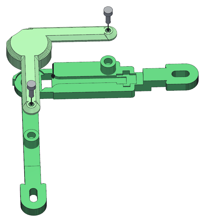
- Plug the cable onto the module before the cover goes on: with the cover down, the connector is no longer reachable.
- The cover goes on over it and takes two M2.5 × 8 screws into the M2.5 inserts you put in the bracket in chapter 2. It rests on the bracket, never on the module: the module is held by its own two screws.
Step 4 Route the sensor cable down into the box
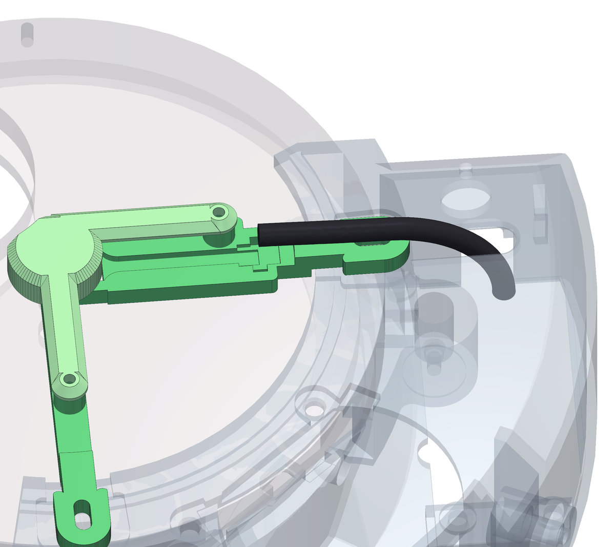
- The Ø5.6 mm cable leaves the cover along the open channel in the arm of the bracket - it lies in from above, it does not thread through anything - and drops into the box through the opening in its wall.
- Keep it easy: nowhere should it bend tighter than about 22 mm radius.
- Close the cable tie you threaded under the arm over the cable, on the flat seat between the two slots, and cut the tail. It is what keeps a pull on the cable away from the solder pads of the sensor board - the weakest joint of the whole chain.
- Leave enough slack inside the box for the panel to hang down on its cable when you open it again. A cable cut to exactly the right length is a cable you tear out the second time you go in.
Step 5 Plug everything in and close the panel
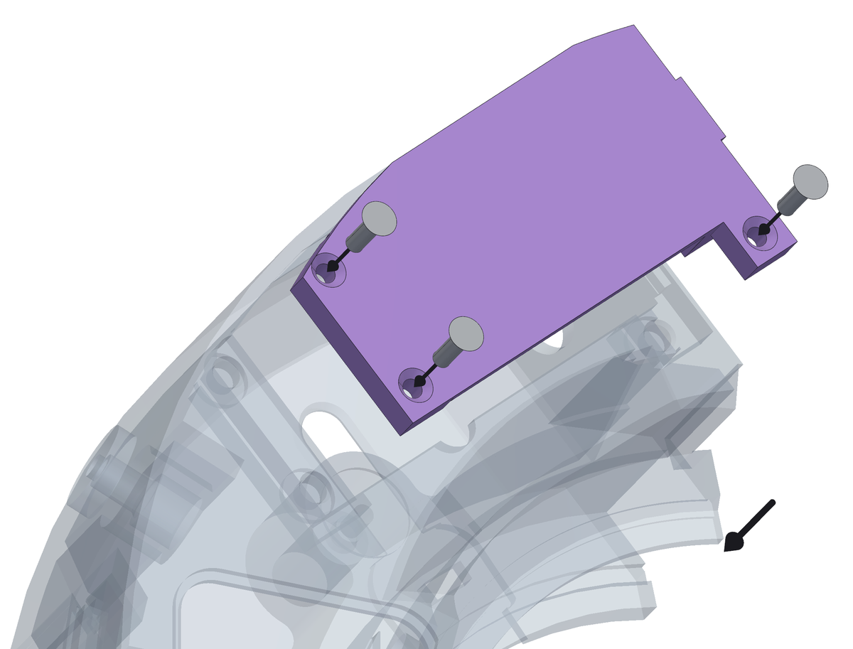
- Three cables meet at the board: the motor, the sensor, and the connector and LED in the head of the box. Plug them all in with the panel still hanging free, where you can see what you are doing.
- Offer the panel up into its step in the underside of the box and push it flat. It sits in a rebate, so it will only go one way.
- Three M3 × 8 countersunk screws into the inserts around the opening. Start all three, then pull them down together.
- Take the panel off and put it back once, now, before the machine goes anywhere. What goes wrong with a lid is never the first time it is closed - it is the second time it is opened.