
Chapter 2
Heat-set inserts
Before anything is assembled, the printed parts get their brass inserts. Doing them all in one sitting is not just convenience: some of them can only be reached while the part is bare, and the pivot insert is the clearest case - once the arm hangs on that pivot, no soldering iron will ever reach it again. The clutch's insert goes in here too, last.
What you need
Parts
- 1×box and collarprinted, ASA
- 1×M3 insert · pivotM3 heat-set insert, Ø5.0 × 3.0 mm M
- 3×M3 insert · panel screwM3 heat-set insert, Ø5.0 × 3.0 mm M
- 2×M3 insert · hatch coverM3 heat-set insert, Ø5.0 × 3.0 mm M
- 2×M3 insert · grip coverM3 heat-set insert, Ø5.0 × 3.0 mm M
- 1×M4 insert · preload screwM4 heat-set insert, Ø6.3 × 8.1 mm M
- 1×board panelprinted, ASA
- 2×M2 insert · board postM2 heat-set insert, Ø3.6 × 4.0 mm M
- 1×M2.5 insert · board post, head endM2.5 heat-set insert, Ø4.6 × 4.0 mm M
- 1×sensor bracketprinted, ASA
- 2×M2.5 insert · sensor coverM2.5 heat-set insert, Ø4.6 × 4.0 mm M
- 1×clutch hubprinted, ASA
- 1×clutch tyreprinted, TPU 87A-95A
- 1×M3 insert · clutch grub screwM3 heat-set insert, Ø5.0 × 3.0 mm M
Tools
- soldering iron with heat-set tips for M2, M2.5, M3 and M4 inserts
- a square block to press against, or a steady hand
Step 1 The collar: the pivot insert, first of all
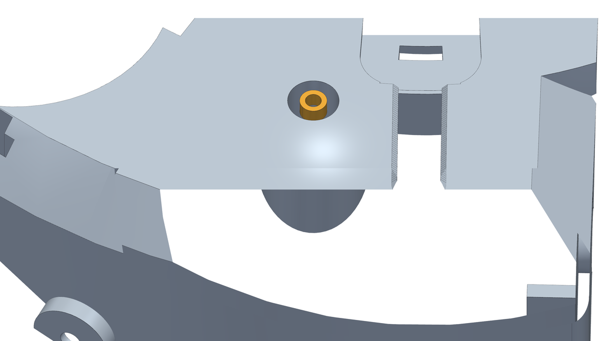
- Put the collar in front of you with the telescope side up - the side the pivot boss is on.
- Melt the Ø5.0 × 3.0 mm M3 insert into the end of the pivot, flush with the face around it.
- Do this one before the others and before anything else is assembled. The arm hangs on this pivot and the screw that holds it comes from the far side: once the collar is on the wheel there is no way back to this hole.
- Keep the iron straight along the pivot. The hole is on the axis of a Ø5 mm post, and an insert that goes in crooked takes the screw crooked with it.
Step 2 The box: three inserts for the panel screws
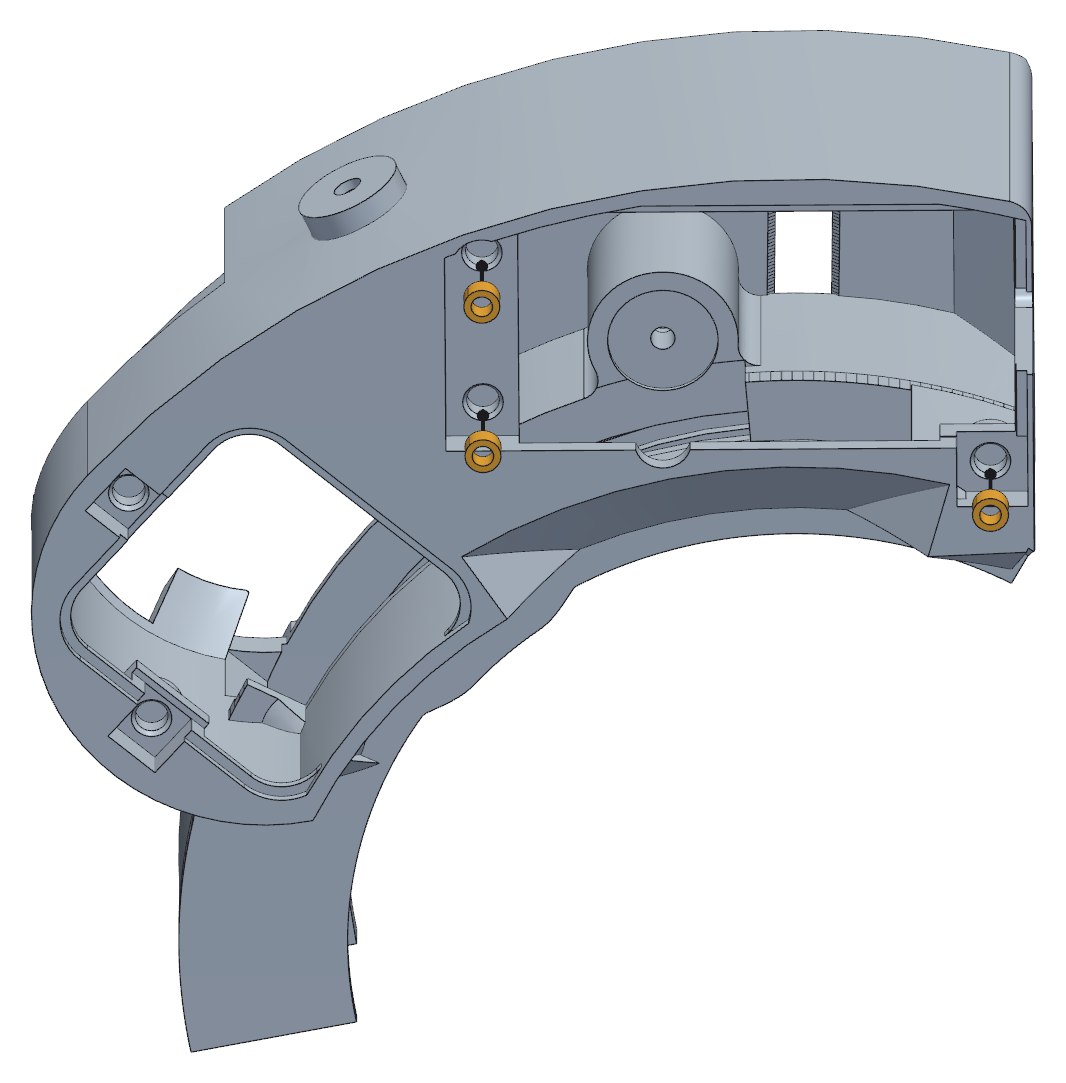
- The box takes three M3 inserts, all on the outside face around the panel opening.
- Same Ø5.0 × 3.0 mm inserts again.
- The panel screws are countersunk and pull the panel flat against this face, so what matters here is that the inserts end up flush and not proud.
Step 3 The box: two inserts for the motor hatch
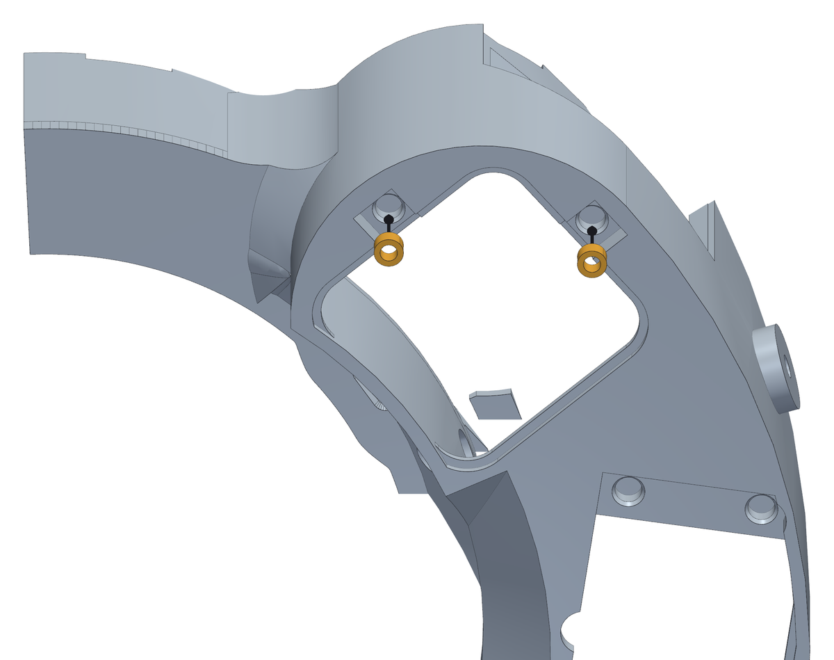
- Two more Ø5.0 × 3.0 mm M3 inserts, on the outside face of the floor, in the two pockets beside the square hatch under the motor.
- They go in from below, like the panel ones, and end flush with the ceiling of their pocket: the hatch cover's two ears sit in those pockets and its countersunk screws pull them flat.
Step 4 The collar: the insert for the cover screw
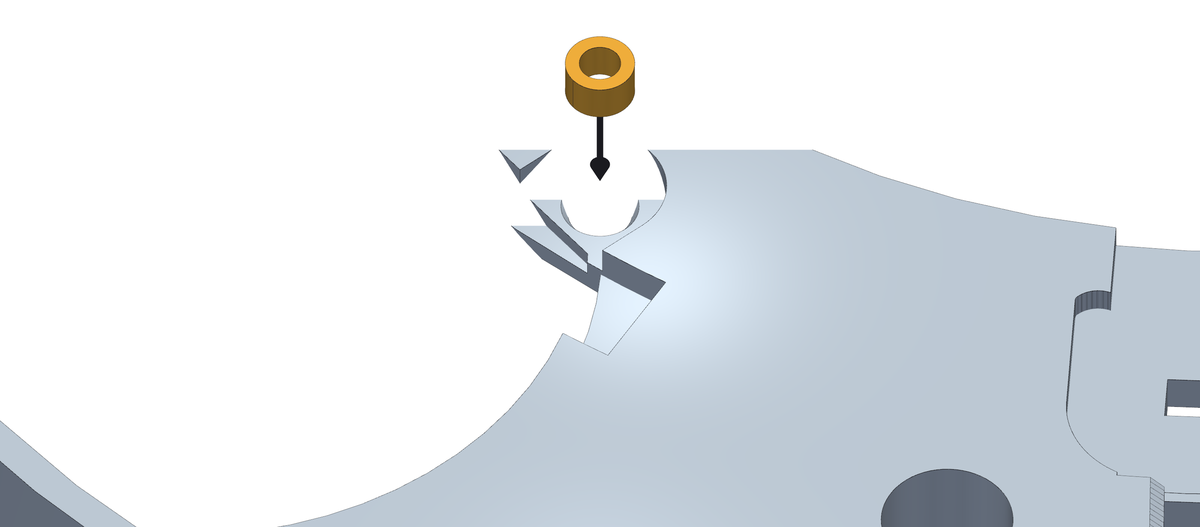
- One more Ø5.0 × 3.0 mm M3 insert, into the small round pocket in the top of the collar, beside the big opening over the motor.
- It goes in from above, straight down, flush with the floor of the pocket. The cover's tab sits in that pocket and its screw comes down into this insert.
Step 5 The collar: the insert for the second cover screw
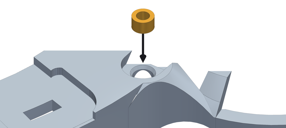
- A second Ø5.0 × 3.0 mm M3 insert for the cover, in the other small round pocket in the top of the collar: the one at the corner where the collar meets the curved wall round the motor, on the side away from the electronics.
- Straight down like the first, flush with the floor of the pocket.
Step 6 The box: the M4 insert for the preload screw
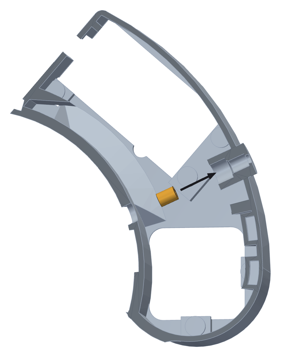
- One more goes into the box, and it is the odd one: an M4 insert, Ø6.3 × 8.1 mm, into the outer wall behind the spring seat.
- It goes in horizontally, from inside the box, along the axis of the spring: the iron comes across the compartment from the wheel side, through the small round hole in the inner wall, and pushes the insert out towards the outer wall. Keep the iron level. (If your insert tip is too short to reach - on the reference build the 8 mm one was - use a nail instead, heated with the iron: that is how this insert went in.)
- This is the insert the preload grub screw lives in, and the spring pushes on it with 13.5 N for the life of the machine. It is worth the extra minute of getting it square.
Step 7 The panel: three small inserts for the board
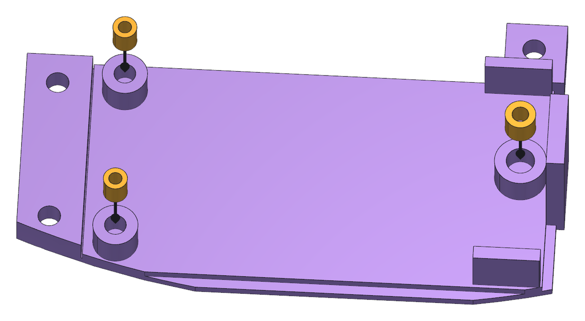
- The board panel takes three inserts on its inside face, on top of the posts the board will sit on.
- Two are M2, Ø3.6 × 4.0 mm, and the one at the head end is M2.5, Ø4.6 × 4.0 mm. They are not interchangeable - fit the M2.5 tip for that one.
- These are small. Let the iron do the work and stop as soon as the brass is level with the post: a post pushed too far melts short, and the board then sits on the panel instead of on the posts.
Step 8 The sensor bracket: two inserts for its cover
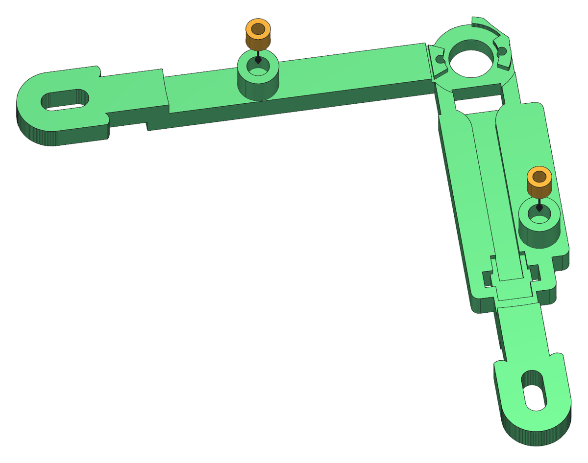
- Last, the sensor bracket: two M2.5 inserts, Ø4.6 × 4.0 mm, one at each end of the cover seat.
- The cover screws down onto these two and holds the sensor board against the bracket, so keep them square.
Step 9 The clutch: the M3 insert for its grub screw
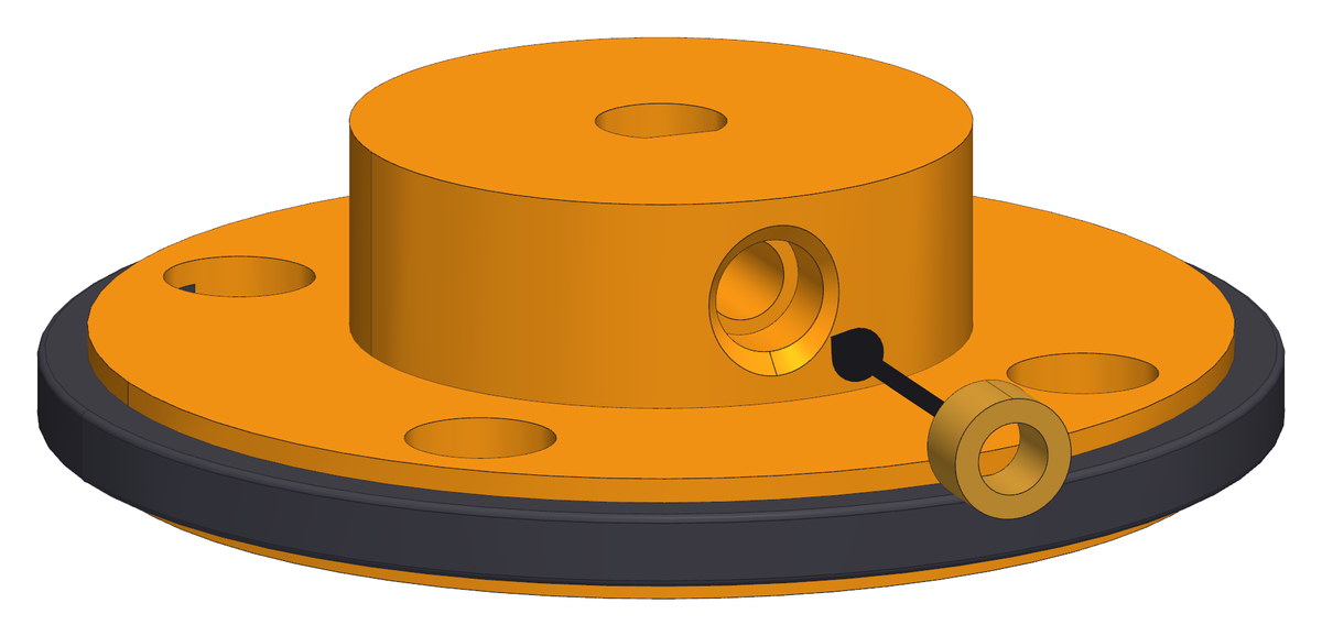
- Take the printed clutch - off the machine, in your hand - and find the channel in the side of the hub. It runs from the outside straight to the shaft bore.
- Push the Ø5.0 × 3.0 mm M3 insert into the channel with the M3 tip, brass first.
- Keep the iron in line with the channel. The channel is open all the way to the outside for that reason: the shoulders of the tyre reach Ø46 mm, and an iron coming in at an angle lands on them instead of on the insert.
- The insert stops by itself where the channel narrows into the clearance hole for the grub screw. Do not push it past that: there is no way to get it back out.