
Chapter 0
Parts, tools and printing
Before the first insert goes in, here is the whole machine, everything it is made of and everything you need to have on the bench. The colours you see here are the colours every part keeps for the rest of the guide: if you can tell the arm from the collar in this picture, you can tell them apart fifteen steps later, half hidden behind the box.
What you need
Parts
- Printed parts
- 1×box and collarprinted, ASA, 124.9 g — the electronics door on the plate: a 143 × 143 mm bed, the part turned 46° on it, 60 mm tall; or the face of the GX12 connector on the plate: 133 × 133 mm, turned 145°, 140 mm tall
- 1×armprinted, ASA, 14.5 g — top face on the plate - body and motor plate end on the same plane
- 1×clutch hubprinted, ASA, 11.8 g — axis vertical, collar face on the plate
- 1×clutch tyreprinted, TPU 87A-95A, 1.7 g — co-printed with the hub
- 1×sensor bracketprinted, ASA, 10.4 g — the flat underside, with the pad, on the plate
- 1×sensor coverprinted, ASA, 3.2 g — outer face on the plate
- 1×board panelprinted, ASA, 9.9 g — outer face on the plate
- 1×spring cupprinted, ASA, 0.3 g — flat back on the plate, dish up
- 1×grip coverprinted, ASA, 11.7 g — upside down, top face on the plate
- 1×motor hatch coverprinted, ASA, 5.2 g — outer face on the plate - the face in sight, flush with the floor
- 1×pivot washerprinted, ASA, 0.2 g — flange on the plate, sleeve up
- 4×magnet spacerprinted, ASA, 0.6 g — four of them - it is a part that gets lost
- 1×front gasketprinted, TPU 87A-95A, 0.7 g — flat on the bed, lip up (co-print it with the collar if you have a multi-material printer)
- 1×rear gasketprinted, TPU 87A-95A, 0.7 g — flat on the bed, lip up (co-print it with the collar if you have a multi-material printer)
- Mechanics to buy
- 2×F695ZZ bearingF695ZZ flanged, 5 × 13 × 4
- 1×M3 grub screw · clutchM3 × 10 headless hex GRUB SCREW (10.0 mm from the shaft flat to the insert)
- 1×M4 grub screw · preloadM4 × 14 headless hex GRUB SCREW (12.1 mm from the back of the spring cup to the mouth of the boss)
- 2×M2.5 insert · sensor coverM2.5 heat-set insert, Ø4.6 × 4.0 mm M
- 1×M2.5 insert · board post, head endM2.5 heat-set insert, Ø4.6 × 4.0 mm M
- 2×M2 insert · board postM2 heat-set insert, Ø3.6 × 4.0 mm M
- 2×M3 insert · grip coverM3 heat-set insert, Ø5.0 × 3.0 mm M
- 1×M3 insert · clutch grub screwM3 heat-set insert, Ø5.0 × 3.0 mm M
- 2×M3 insert · hatch coverM3 heat-set insert, Ø5.0 × 3.0 mm M
- 3×M3 insert · panel screwM3 heat-set insert, Ø5.0 × 3.0 mm M
- 1×M3 insert · pivotM3 heat-set insert, Ø5.0 × 3.0 mm M
- 1×M4 insert · preload screwM4 heat-set insert, Ø6.3 × 8.1 mm M
- 1×magnetØ8 × 1, DIAMETRICALLY MAGNETISED
- 1×stepper motorNEMA 14 14HS10-0404S
- 1×preload springcompression spring, wire 0.9, Ø6.7 outside, 13.5 mm free, 11.1 mm fitted, 5.7 N/mm (the prototype's came from a clothes peg)
- 1×M2.5 screw · boardM2.5 × 6, hex socket head (5.5 mm needed under the head)
- 2×M2.5 screw · sensor coverM2.5 × 8, hex socket head (7.0 mm needed under the head)
- 2×M2 screw · boardM2 × 6, countersunk head (5.5 mm needed under the head)
- 2×M2 screw · AS5600 moduleM2 × 4, countersunk head (4.0 mm needed under the head)
- 2×M3 screw · collar clampM3 × 14, hex socket head (12.4 mm needed under the head)
- 2×M3 screw · grip cover, knurled headM3 × 6, hex socket head (6.0 mm needed under the head)
- 2×M3 screw · hatch coverM3 × 8, countersunk head (8.0 mm needed under the head)
- 4×M3 screw · motorM3 × 8, hex socket head (8.0 mm needed under the head)
- 3×M3 screw · panelM3 × 8, countersunk head (8.0 mm needed under the head)
- 1×M3 screw · pivotM3 × 20, hex socket head (20.0 mm needed under the head)
- Electronics to buy
- 1×U1 Seeed XIAO ESP32-S3native USB-C; FPC antenna on U.FL
- 1×U2 TMC2208 stepstick driver, with its heatsink8+8 pin module, Rsense 0.110 Ω (M, marked R110). A TMC2208, not a TMC2209: see pcb/BOM.md
- 1×C1 electrolytic capacitor47 µF 63 V, Ø6.35 × 13 mm (M) - bulk at the driver's VM, required, and its place on the board matters
- 1×C2 electrolytic capacitor47 µF 63 V - optional, bulk at the 12 V input
- 1×R1 resistor10 kΩ ¼ W - pull-up on EN, not in series
- 1×R2 resistor1 kΩ ¼ W - in series on TX; leave it out if the driver module already has one
- 1×R3 resistor1 kΩ ¼ W - in series with the LED
- 1×J1 JST XH socket, 4 wayspitch 2.5 - motor phases A± B±, one connector; with its plug
- 1×J3 screw terminal block, 2 wayspitch 5.08 - 12 V in
- 1×J4 JST XH socket, 4 wayspitch 2.5 - sensor: SDA, SCL, VCC, GND; with its plug
- 1×J5 JST XH socket, 2 wayspitch 2.5 - status LED; with its plug
- 2×female pin strip, 1 × 7round pins through both sides, body 3.0 mm - the XIAO's socket
- 2×female pin strip, 1 × 8the driver's socket
- 1×perfboarddouble-sided, pitch 2.54, cut to 70 × 30.3 (24 × 10 holes)
- 1×U3 AS5600 magnetic encoder moduleround Ø16.85 flattened to 15, a row of 8 pads; needs the VDD5V-VDD3V3 bridge, after which it no longer takes 5 V
- 1×C3 ceramic capacitor100 nF (104), 16 V or more - on the module's pads, not on the board
- 1×D1 red LED, 3 mmoutside the board; if it comes pre-wired for 12 V, take its resistor off
- 1×GX12 connector, 2 pinspanel socket with its nut, and the matching plug for the 12 V lead
- 1×CAT5 cablesolid, Ø5.6 - sensor to board
- 1×USB cable, USB-A to USB-C90 degree side elbow at both ends: it goes on and off at every session
- 2×clip-on ferriteson the motor lead and the USB cable, two or three turns through each
Tools
- a 3D printer, and the filament: ASA and TPU, any grade from 87A to 95A (tried on 87A, calculated up to 95A)
- soldering iron with heat-set tips for M2, M2.5, M3 and M4 inserts, and a fine tip for wiring the board
- a Ø2.7 mm drill bit, for one hole of the perfboard
- hex keys: 1.5, 2, 2.5 mm
- a PH0 screwdriver and a 2 mm flat screwdriver
- a 14 mm spanner, for the nut of the GX12 connector
- a caliper, to check what came off the plate
- a 2.5 mm cable tie, for the sensor cable
- a drop of glue for the magnet: cyanoacrylate or epoxy
- a computer with Python 3.12 and Chrome or Edge, and a USB-C cable
- any ESP32 board on a breadboard, to set the air gap
- the 12 V supply and its GX12 lead, for the first checks
- a square block to press the inserts against
- a flat, clean surface to press the bearings against
- 2 × M2 × 4 screws, cylinder or countersunk head, for the air gap feet
- a screwdriver to fit the screws of the wheel's detent
Step 1 What you are building
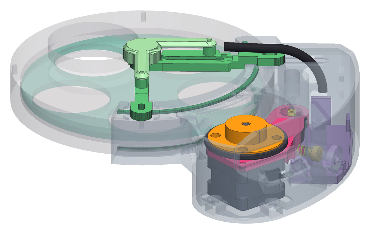
- A manual filter wheel, motorised: the printed parts clamp around the wheel you already own, and they come off again without cutting anything. It was designed around a five-position StarDikor for 2-inch filters - that is the wheel in every picture - and a different wheel is a handful of parameters, not a redesign.
- The stepper hangs under an arm that swings on a pivot, and a spring pushes the arm so that the clutch presses on the rim of the filter disc. Everything else - the sensor, the board, the box - hangs off those few parts.
- The wheel body itself goes on last, and the reason is measured: above the clutch there is no room to start it onto the shaft once the wheel is in place.
Step 2 The parts you print
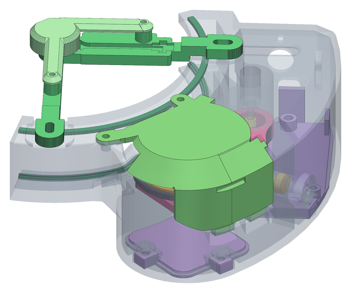
- 14 printed parts: ASA for what stays, TPU for the tyre and the gaskets - any grade from 87A to 95A: the machine has been tried on 87A only, and up to 95A it is calculated, not tried. Masses and print orientations are in the list above - the orientation is part of the design, not a choice left to the slicer.
- Print in PETG first if you are prototyping: it is easier, and the tolerances in this project were measured on ASA, so a PETG part may fit slightly differently.
- The parts are shown here where they end up, not laid out on a plate, and the box is drawn see-through so that what it covers can be seen. Look at the colours: they do not change from here on.
Step 3 And the mechanical parts you buy
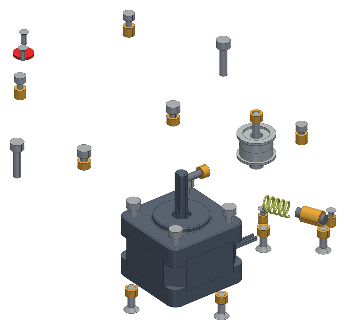
- The motor, two bearings, the magnet, the spring, and the screws and inserts - shown here on their own, without the printed parts around them, so you can see how few there are and where each one lives.
- Steel is the screws and the bearings, brass is the heat-set inserts: two colours, because in a picture of a machine they would otherwise be the same grey smudge.
- The electronics are bought too, and are in the list above, under their own heading: they have no picture here because they are wired on the bench before they meet the machine, in chapter 9.
- Check the magnet before you buy it: it must be diametrically magnetised. One magnetised through its thickness looks identical, is easy to buy by mistake, and gives the sensor nothing to read.
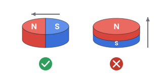
Left, the one to buy: N and S side by side, the field across the diameter. Right, the one that looks the same and does not work: N on top, S underneath.